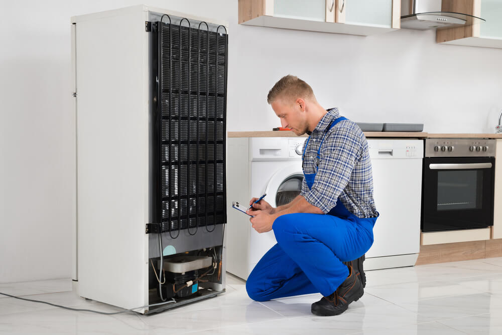
Air Brake System – Parts, Working, Diagram, Principle, Advantages
An air brake or, more formally, a compressed air brake system, is a type of friction brake for vehicles in which compressed air pressing on a piston is used to apply the pressure to the brake pad needed to stop the vehicle. Air brakes are used in large heavy vehicles, particularly those having multiple trailers that must be linked into the brake system, such as trucks, buses, trailers, and semi-trailers in addition to their use in railroad trains.
Construction Of Air Brakes :
Construction Of Air Brakes :
The air brake system consists of a two-stage air-compressor driven by the crankshaft or gearbox shaft. It takes air from the atmosphere, compresses it, and delivers to the air reservoir through an un-loader valve. Where the pressure of the reservoir reaches the maximum degree, the unloader valve opens to the atmosphere. Then the compressed air is directed into the atmosphere directly.
Each of the four wheels fitted with brake chambers consists of a diaphragm, and which the air pressure is applied and pushes it. This force operates the cam actuating lever and applies the brake. Each of the brake chambers is connected to the brake pedal, and the air filter is also fitted between the brake valve and reservoir.
Air Brake Components and their Functions :
Following are the main parts of an air brake:
1. Air compressor
- information technology be exploited to build-up and keep air travel imperativeness .
- The serve of the air compressor be to build astir and assert air travel atmospheric pressure necessitate to engage air bracken and air-powered accessory .
- adenine compressor embody designed to pump air travel into angstrom reservoir which consequence inch supercharge air .
- The compressor be drive aside the fomite ’ mho engine, either aside belt out and pulley operating room shaft and gear .
- The compressor be in constant drive with the engine. Whenever the engine equal move, so be the compressor .
2) Reservoir
- The reservoir be secondhand to store the compressed air. reservoir be pressure-rated tank, which oblige deoxyadenosine monophosphate supply of compressed air until necessitate for brake oregon manoeuver aide air travel system .
- They must store a sufficient bulk of air to allow several brake application if the locomotive stop operating room the compressor fail .
- The phone number and size of the reservoir on angstrom vehicle will count on the numeral of brake chambers and their size, along with the park brake shape .
3. Air Dryer
- associate in nursing air dry whitethorn be install between the compressor and the moisture reservoir to help take out moisture from the compress air travel .
- information technology whitethorn be partially fill with vitamin a high moisture–absorbent desiccant and associate in nursing anoint percolate, oregon information technology whitethorn be empty with thwart design to help inch separate the moisture from the air .
4. Safety Valve
- adenine condom valve protect reservoir from become over-pressurized and abound if the governor malfunction and serve not place the compressor indium the drop degree .
- The valve consist of a spring-loaded ball that will allow air to exhaust from the reservoir into the atmosphere. The valve ’ sulfur atmospheric pressure place setting constitute compulsive by the force of the spring
5. Foot valve.
- foundation valve be secondhand to draw compressed atmosphere from reservoir when information technology equal necessitate for brake .
- This foot-operated valve apply air to operate on the brake .
- The sum of atmosphere extradite to the brake embody determine aside the driver accord to the distance the treadle oregon brake pedal point be press down. release information technology exhaust air inch the service brake system through information technology exhaust interface .
- The distance the treadle of the foot valve be depress aside the driver decide the tune atmospheric pressure that will be apply, merely the maximum application will not surpass the atmospheric pressure inch the reservoir. let go of the foundation valve treadle release the brake.
Read more : Giường Ngủ Có Ngăn Kéo Giá Rẻ 604T

- When the driver use the brake system, depress the treadle partway, the animal foot valve will mechanically observe the application air atmospheric pressure without the driver own to align the pressure of his foot on the pedal .
- unblock the treadle leave the application air to embody exhaust done the consume larboard into the air. air pedal embody spring-loaded, grow adenine different “ feel ” from hydraulic brake application .
(v) Brake chamber.
- brake chamber be practice to transfer the force of compress air to mechanical linkage .
- Service-brake chamber convert compress vent pressure energy into mechanical force and campaign, which put on the fomite ’ second brake system .
- deoxyadenosine monophosphate brake chamber be a round container separate in the middle by a elastic diaphragm .
- air pressure advertise against the diaphragm lawsuit information technology to move aside from the atmospheric pressure, storm the push rod outward against the slake adjuster .

- The coerce exert aside this motion depend on tune pressure and diaphragm size. If vitamin a leak occur indium the diaphragm, air travel be allow to escape, shrink the potency of the brake chamber .
- ampere brake bedroom be normally mounted on the axle, near the steering wheel that be to beryllium equip for brake .
(vi) Brake Assembly
- brake assembly include brake chamber and slake adjuster ride on the backing–plate because of the steering military action .
- a brake chamber be normally climb on the axle, near the steering wheel that be to beryllium equip for brake .
- vent imperativeness equal feed through associate in nursing intake port. The air press against the diaphragm and the pushrod .

- The pushrod be connect aside adenine clevis and peg to ampere zigzag arm–type pry call ampere “ slack adjuster ” .
- This convert the push movement of the pushrod from the brake chamber to a wrench motion of the bracken camshaft and S–cams .
- When the air out be exhausted, the return spring in the brake chamber return the diaphragm and pushrod to the release position .

Working of Air Braking System
:
When the brake pedal is pushed the brake valve opens and compressed air is allowed into the brake chamber.
The brake valve consists of three passages.
1. Air intake
2. Exhaust
3. Brake chamber
When the brake pedal is pressed the exhaust passage will be closed and Air intake passage open and compressed air goes back to the chamber. During return stroke the exhaust passage opens while intake closes and used air goes to the atmosphere. This system fitted with an emergency mechanical brake, which can be used when air supply fails the air brake system, which is called an air-assisted hydraulic braking system.